26 May 2024
After receiving the CAMIT grant, I’ve spent the past few weeks refining how to bring Tangible Dreams to life. What started as an idea — to let people physically manipulate neural networks — is now moving toward reality. In this post, I’ll share the mathematical foundation behind the project, a real-time software prototype, and the initial design for the physical hardware.
At the heart of Tangible Dreams is a type of neural network called a Compositional Pattern-Producing Network (CPPN). Unlike typical neural networks, which are trained on data to optimize an objective, the CPPN in Tangible Dreams is not trained at all. Instead of relying on a learning algorithm to modify its weights and architecture, visitors themselves will take on that role—shaping the network structure and parameters through physical interaction, driven by their own curiosity rather than a predefined loss function.
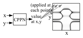
A CPPN generates an image by mapping each pixel’s coordinates—(x, y), distance from center, or other spatial features—to a color value. For every point in space, the network decides what should appear there. The result is a rich, continuous pattern produced by evaluating this fixed network across all pixels.
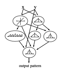
What makes CPPNs powerful is how they build complexity from simplicity. The network consists of three types of nodes: input nodes that provide spatial information (e.g., x, y coordinates, distance from center), middle nodes that each apply a mathematical function (sine, cosine, gaussian) to transform their inputs, and output nodes that finally turn previous computations into RGB values for each pixel.
Each middle and output node in the network receives weighted inputs from other nodes, combines them (typically as a weighted sum), applies an activation function, and passes the result forward. This process can be expressed mathematically as:
\[\text{output} = \sigma \left( w_1 \cdot x_1 + w_2 \cdot x_2 + w_3 \cdot x_3 + b \right)\]Where \(\sigma\) is the node’s activation function (like sine, sigmoid, or gaussian), \(w\) values are weights, \(x\) values are inputs from other nodes or coordinates, and \(b\) is a bias term.
By composing these simple functions together, CPPNs can generate an infinite variety of patterns with natural-looking symmetry, repetition, and complexity—all without explicitly programming these properties. The connections between nodes and their weights determine what patterns emerge, allowing for both structured and organic-looking results. I really recommend reading the original paper from Ken Stanley.
Before building the physical system, I needed to demonstrate that the idea could work—that I could run a CPPN interactively, in real time, at a high resolution. One challenge quickly became obvious: processing every pixel individually is very slow. For an HD image (1920×1080 pixels), the network has to process over two million pixel coordinates for every single frame! To make this possible, I implemented the network using JAX, a Python library that lets you run massive computations in parallel on a GPU. With JAX I could parallelize the network evaluation across all pixels and achieve smooth, real-time rendering. I also needed a way to control the network parameters during the demo. Since the physical nodes aren’t built yet, I use a MIDI controller to simulate the system:
This setup gave me a prototype that was both real-time and interactive—letting me demonstrate the core experience that Tangible Dreams will deliver.
The next step is designing the physical system. The main idea is simple: Each node—inputs, middles, outputs—becomes a small electronics box. Cables between boxes represent connections and knobs control various parameters of the node.
Importantly: The actual neural network computation happens on a computer, not inside the boxes. The boxes act as sensors—they send information about their current state (connections, weights, biases, activation functions) to the computer. The computer then quickly builds the network, runs in on all pixel in parallel and projects the resulting image.
Each box thus contains:
This system keeps the physical part simple and robust: the complexity stays inside the computer, while the user experience remains direct and tactile—plug, turn, adjust, and immediately see the result.
..at least that’s the plan!
If you’re curious about behind-the-scenes updates as I build, follow me on Twitter at @cedcolas!